How To Use
Note
If you’re having any trouble, don’t hesitate to contact us.
Set up Objects
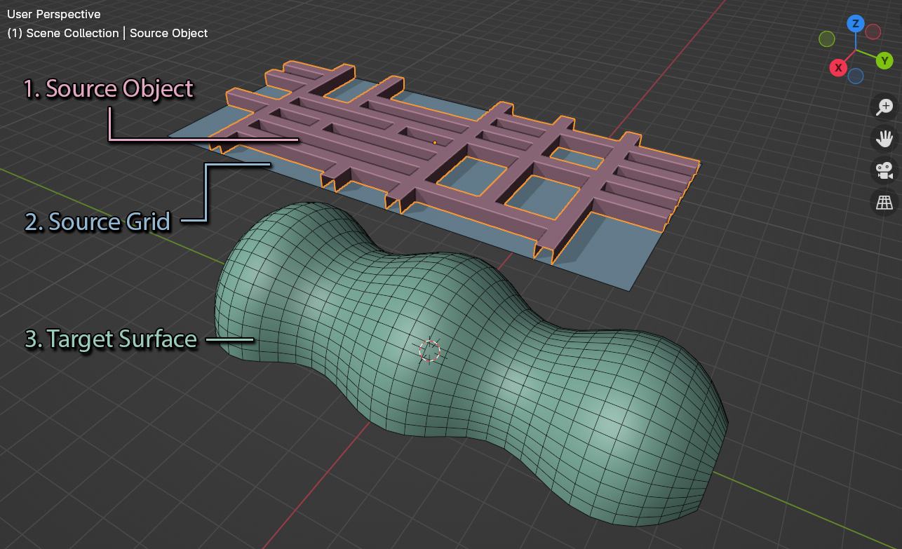
Once installed, for Flowify to work in Blender you will need to create the following objects arranged as above:
The Source Object that you wish to deform.
Note
The deformation will only be as good as an object’s mesh topology (Faces and Edges). You may need to add extra faces, edges or edge loops for the object to bend well.
A flat rectangular Source Grid to use as a reference for the Target Surface. This should be in a relative position to where you want the Source Object mapped to the Target Surface.
Note

Flowify understands a source grid to consist of 4 sided faces with 4 distinct corners and to be entirely flat. Its face direction (or Normals) should also match the Target Surface.
The Source Grid can be a simple single-faced rectangle and does not need to have the same number of faces as the Target Surface.
A Target Surface that can either be:
An grid shape of evenly spaced 4 sided faces with 4 distinct corners, or
A cylindrical shape of evenly spaced 4 sided faces with open ends.
Each surface can have a different number of faces in their rows and columns.
Note
Valid Target Surfaces
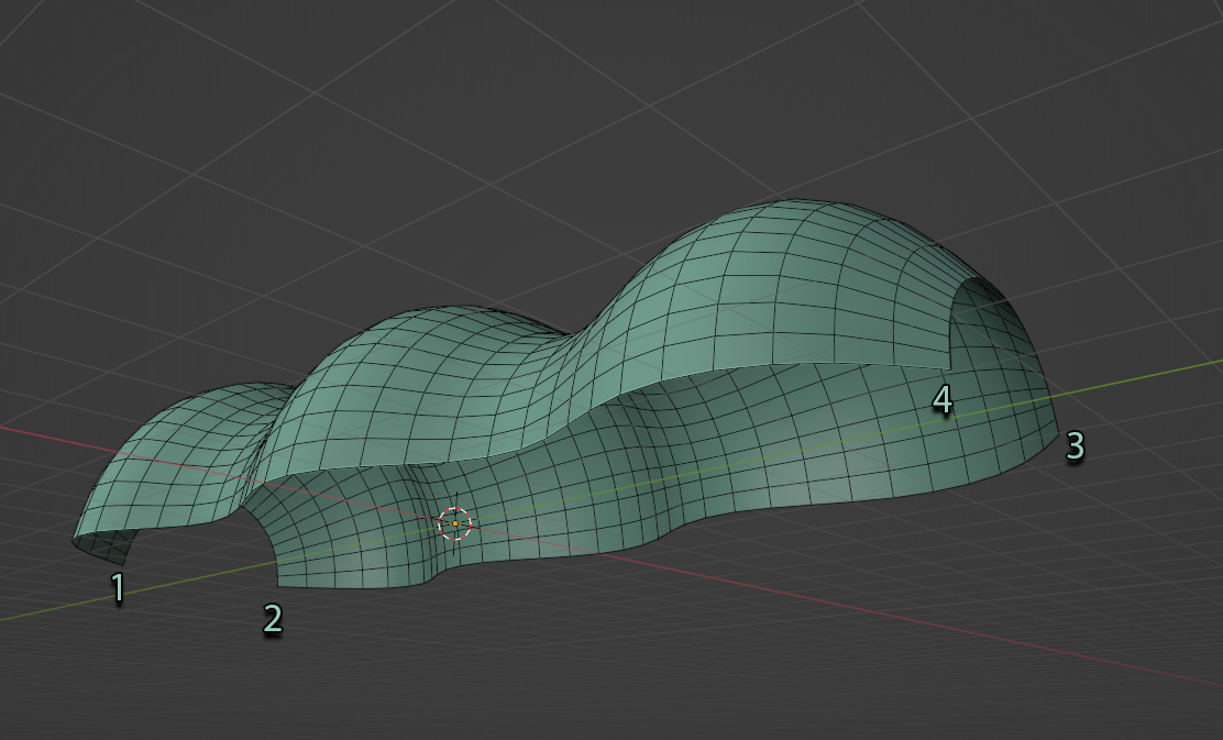
A valid Target Surface shaped like a grid.
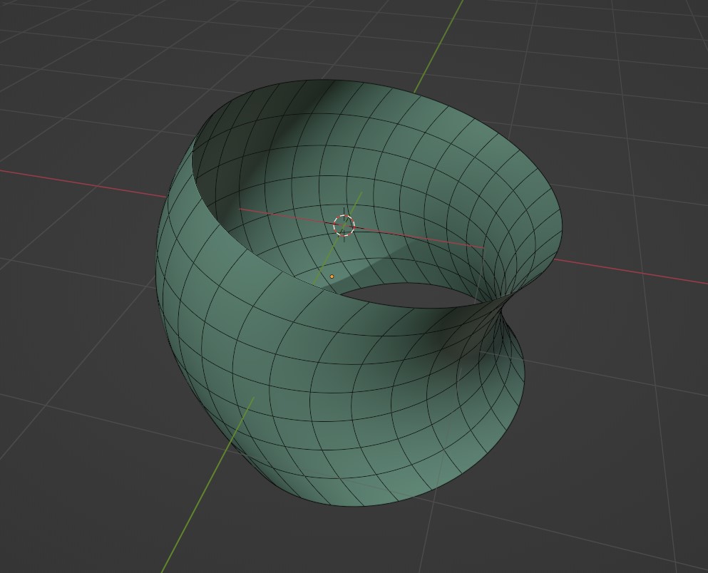
A valid Target Surface shaped like a cylinder.
The vertices of the surface must be evenly spaced for Flowify to work well. Blender’s built in Loop Tools add-on’s Space operation should help with this.
The target surface should also consist of 4 sided faces, with 4 distinct corners for grids and 2 open ends for cylinders. Their face directions (or Normals) should also match the Source Grid.
Warning
If modifiers such as the Array or Solidify modifier have been added to the Target Surface, the add-on may not work properly. Try applying modifiers like the Array/Solidify modifier first. Subdivision Surface modifiers should work, and if you have any issues do contact us.
Step by Step

The Flowify workflow in Blender for grid surfaces

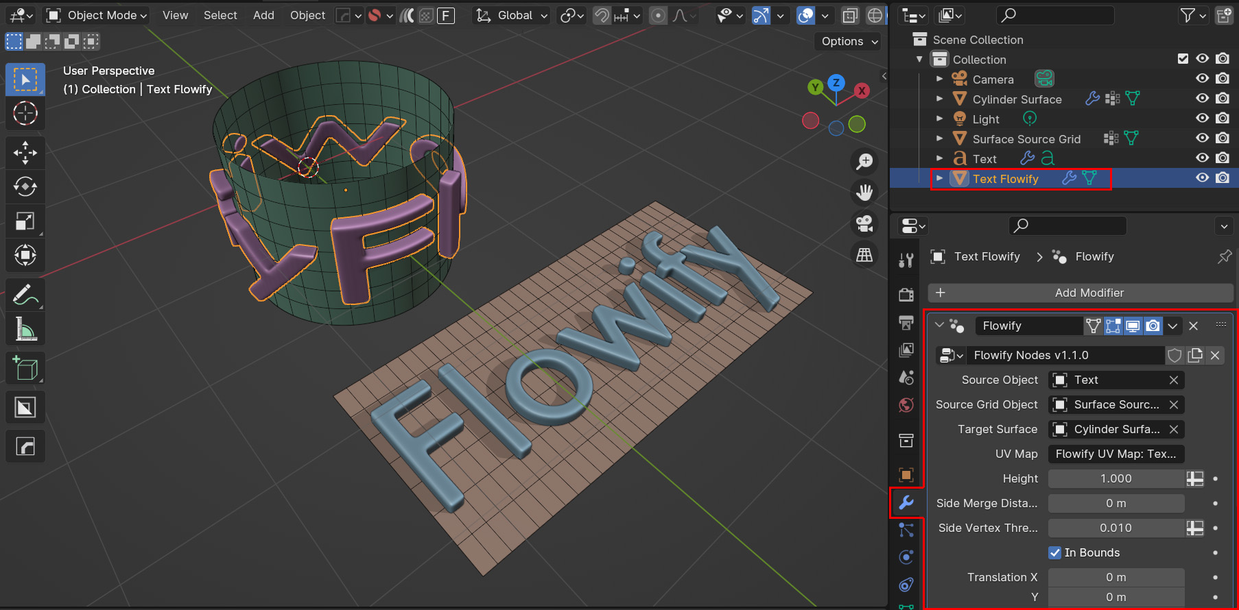
The Flowify workflow in Blender for cylindrical surfaces
The workflow is as follows:
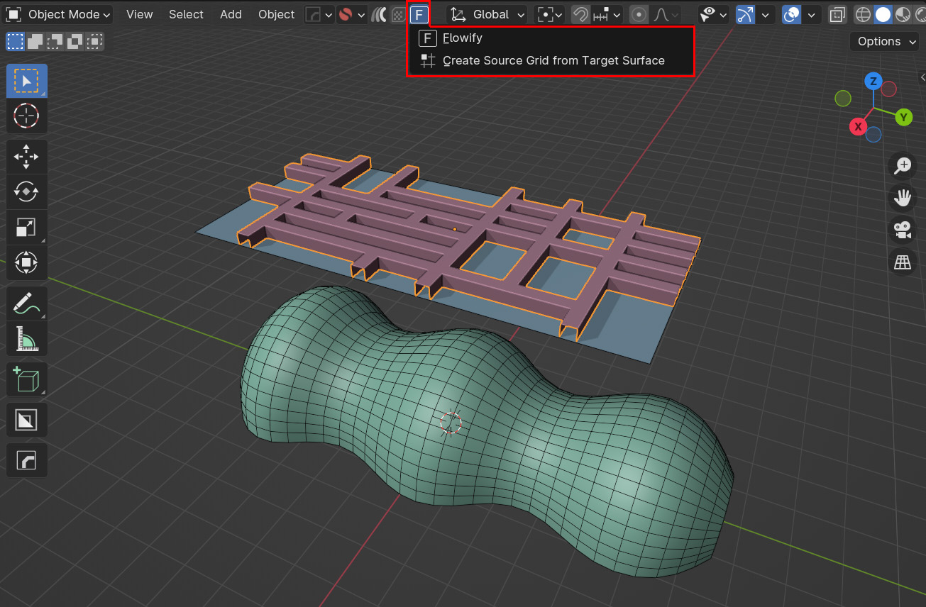
In object mode, select the Source Object(s) and right-click in the viewport. Go to the ‘Flowify’ menu option. Select ‘Flowify’ from the sub-menu that appears.
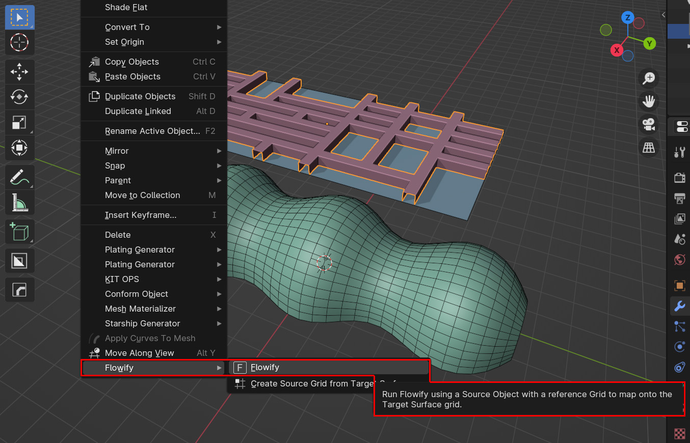
Tip
You can also select the Flowify options by clicking the ‘F’ icon at the top of the viewport.
Tip
You can select multiple source objects at once.
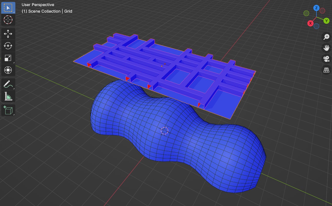
By default, the viewport will change to face orientation mode so you can make sure the face directions (or Normals) of the Source Grid and Target Surface are pointing in the same way (ie the same blue colour).
You can resolve these issues by selecting the faces in edit mode, pressing Alt-N for the Normals menu, and selecting the Flip command. If you need to make the normals more consistent and pointing outside, also try the ‘Recalculate Outside’ option in the same menu.
Note
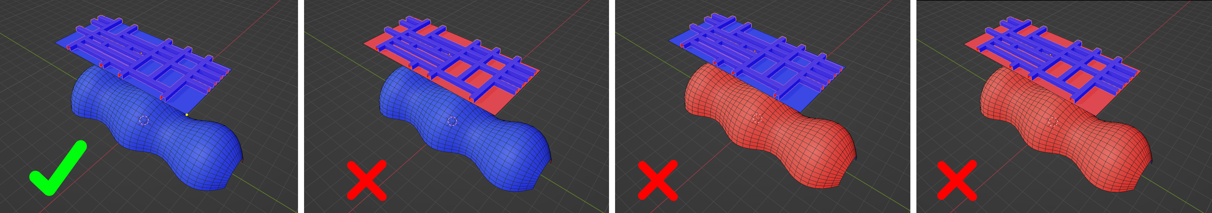
Good and bad face orientations. Both matching sides of the source and the target surface objects should be blue for the add-on to work correctly. Red faces denote faces with their directions (or Normals) pointing in the opposite direction.
Hover the mouse over the Source Grid to detect a corner on the grid. When a corner is detected, a circle will appear on the corner. Click the left mouse button to select this corner and continue.
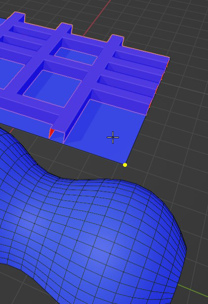
Tip
If the corner is not detected, try hiding any objects in the scene that might be overlapping with the corner.
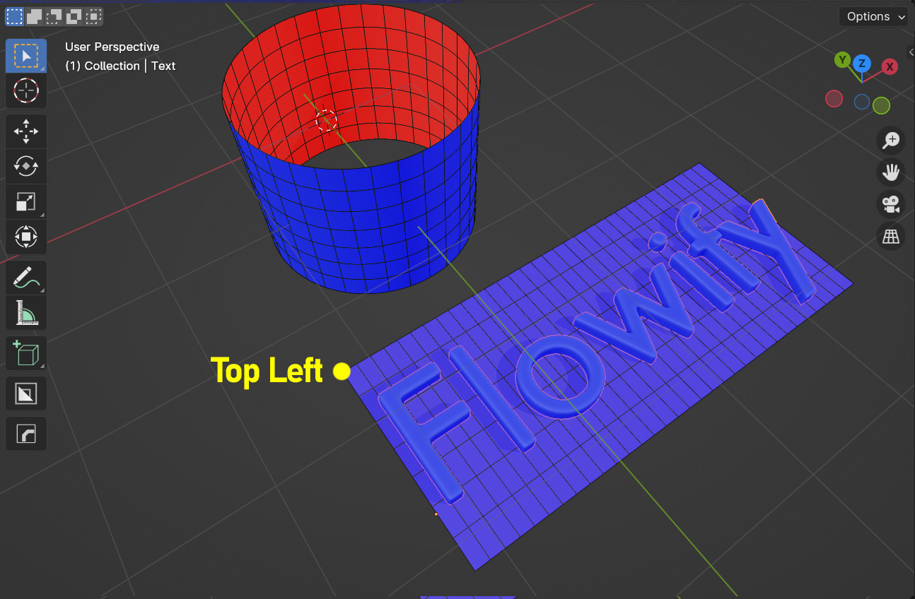
Note
For cylindrical target surfaces, always select the “Top Left” corner of the source grid:
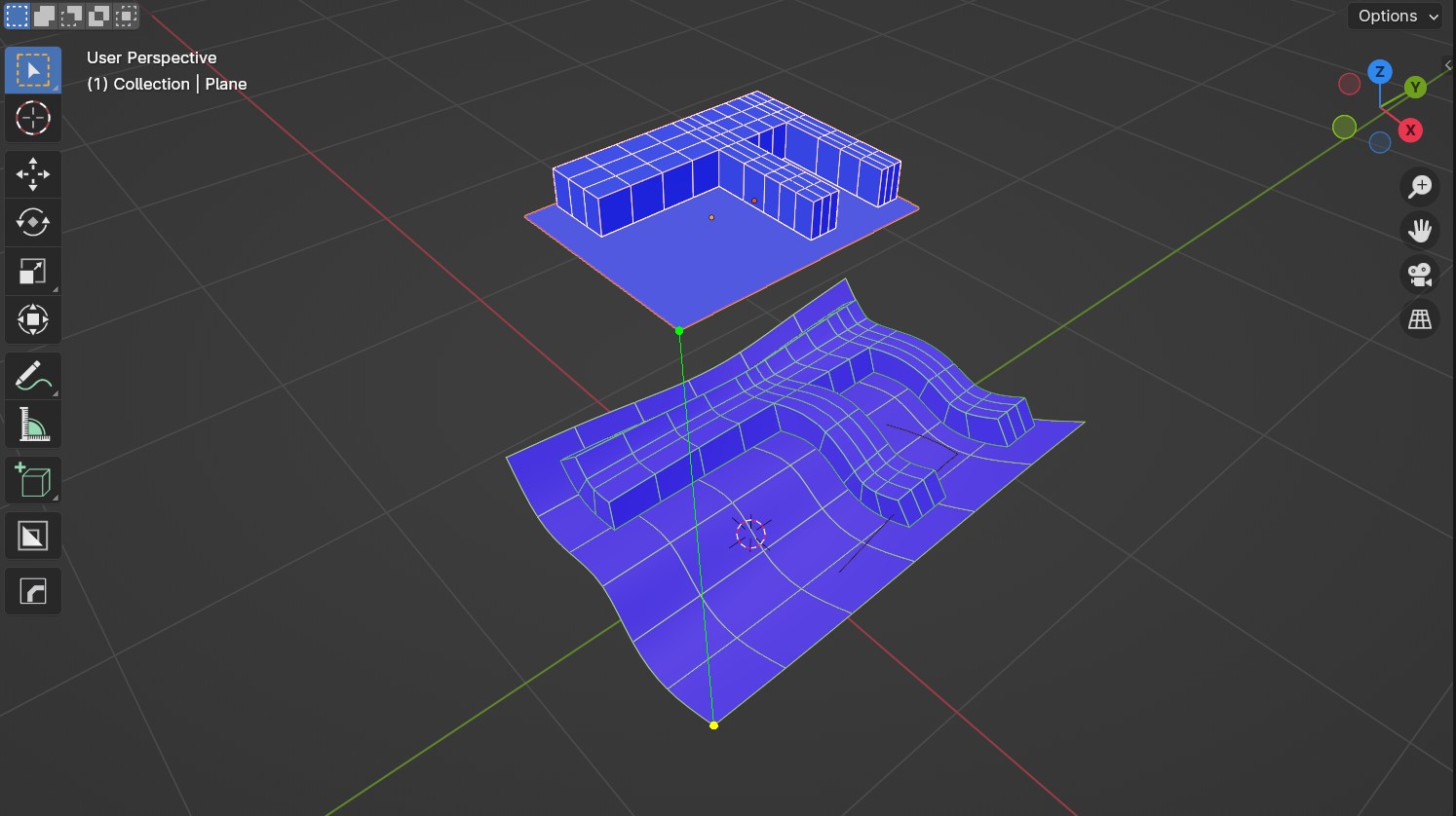
Hover the mouse over the Target Surface and click the matching corner. A line should appear between the Source Grid and the Target Surface, indicating how the mapping will be applied.
Note
Matching Corners
It is important that the corner of the Source Grid is aligned to the same representative corner on the Target Surface to match the correct orientation.
For Grids, the matching corner is the equivilent corner that was selected on the Source Grid.
Grid Corner Selection
For Cylinders, select a point along the ‘top’ end of the surface. This will be the start point of the deformation and match the ‘top left’ corner selected on the Source Grid.

Cylinder Top Rim Selection
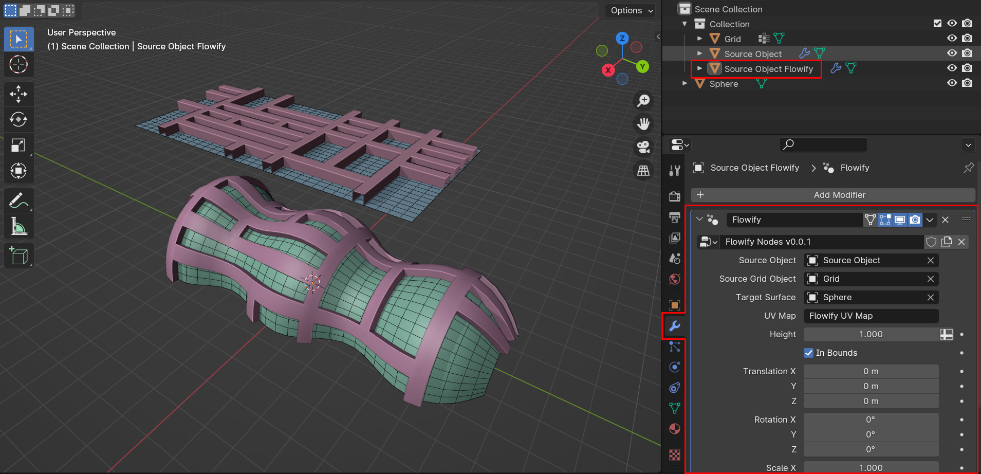
The Source Object should be mapped onto the Target Surface in a new object called Source Object + Flowify. The Source Grid is subdivided into faces that you can use as a reference for the position of the Source Object on the Target Surface.
In this object, there is a Flowify Modifier which has additional settings:
Note
Check out the Tips and Troubleshooting section and don’t hesitate to contact us if you are having issues.